
Coordination · 9 min read
Architecture and structure: a rigorous workflow to synchronise models
By Mickael Quinart · 9 October 2026
How architects and structural engineers exchange models without losing information: milestones, IFC, references and checks.
Hello, I'm Mickael Quinart, BIM/CAD consultant at PALLADION. This article addresses a fundamental BIM issue: coordination between the architect and the structural engineering office. Effective collaboration is the cornerstone of a successful project, preventing design conflicts and optimising the construction process. Let's delve into best practices together.
Two Models, One Reality
The architect and the structural engineering office each produce their own model, with different rationales: one describes the space and envelope, while the other details the structural elements and their sizing. The risk is to have two contradictory truths coexisting.
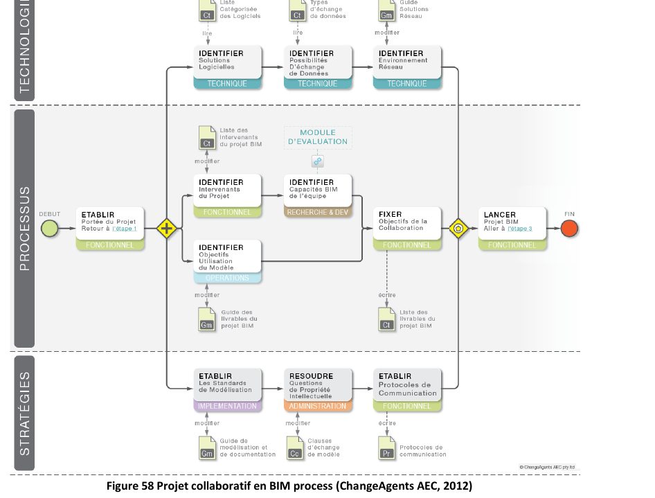
The vision we have here is that of a collaborative process where each stakeholder contributes to a common database, while maintaining control over their own discipline. This is the very essence of BIM as defined by international standards like ISO 19650, which advocates working in a Common Data Environment (CDE) and rigorous information management.
The Principle: Each Owns Their Objects
Clarification of roles and responsibilities is paramount. In BIM, this translates into the concept of "ownership" of objects.
- The architect owns the partitions, joinery, finishes. These elements define the use, aesthetics, and ergonomics of the space.
- The structural engineering office owns the structural walls, columns, beams, slabs, foundations. These elements ensure the stability, resistance, and durability of the structure.
- Each uses the other's model as a reference, without modifying it. This is the principle of "linking" or "hotlinking" in modelling software, where an external model is imported without direct editing, guaranteeing the integrity of each party's data.
This separation of ownership is not a barrier but a framework that ensures clarity and traceability of modifications. It is facilitated by the use of the IFC (Industry Foundation Classes) format, an open and neutral standard that allows the exchange of information models without data loss, regardless of the proprietary software used (e.g., Revit, Archicad for architecture, Robot Structural Analysis, Tekla Structures for structure).
The Exchange Cycle
A well-defined exchange process is essential for fluid and efficient collaboration.
- Issue the Architectural model in IFC at a defined milestone. The architectural model is the starting point, defining volumes and spatial constraints. This milestone must be clearly identified in the project's BIM Execution Plan (BEP), indicating the data maturity (e.g., LOD 200 for a developed design stage).
- Quality control upon receipt (georeferencing, levels, IFC structure). Before any use, it is imperative to check the compliance of the received model. Georeferencing must be identical for all models, levels must correspond to the project's altimetric benchmarks, and the IFC structure must be valid (absence of corrupted objects, correct classification of elements). Tools such as Solibri Model Checker or the free BIM viewer and analysis on the website (mentioned in the "Key Takeaways" section) are valuable for this step.
- Pre-sizing and structural modelling based on the Architectural model. The structural engineering office integrates the architectural model as a reference to design and size the structural elements, respecting spatial and aesthetic constraints.
- Return the Structural model in IFC with observations in BCF. Once the structural model is developed, it is issued in IFC. Observations and modification requests (conflicts, optimisation proposals) are communicated via BCF (BIM Collaboration Format) files. BCF is an open format that allows the exchange of comments, images, and specific views directly linked to objects in the IFC model, thus facilitating communication and problem resolution.
- Integration of structural elements by the architect, arbitration of discrepancies. The architect integrates the structural model into their own reference model and analyses the impacts. Arbitration is often necessary to resolve conflicts between architectural, structural, and sometimes technical (MEP) requirements.
- Joint model review and milestone validation. Model review meetings (often using federated visualisation tools like Navisworks or Trimble Connect) allow all stakeholders to visualise combined models, identify clashes (clash detection), and validate project progress against milestone objectives.
Concrete Case Study in an Engineering Office
In a structural engineering office, we regularly receive architectural models in IFC format. Recently, on a medium-sized office building project, the team followed this exchange cycle.
After receiving the architectural IFC model at the end of the developed design stage, the first step was quality control. We quickly identified that the project origin point was not the same as defined in the BIM Execution Plan and that some levels were offset. Without this verification, all our structural modelling would have been flawed.
Once these corrections were made by the architect, we were able to integrate the model as a reference and begin pre-sizing. While modelling the structural walls, we found that a structural column significantly impacted the layout of a key office on the ground floor. We then created a BCF observation, including a screenshot, a comment explaining the problem, and a proposal to move the column or integrate it into a thicker partition.
The architect could open this BCF directly in their modelling software, view the affected object and the suggestion. After discussion during the model review, it was decided to thicken the adjacent partition to integrate the column, thus preserving the office space. This iterative process, based on structured exchanges via IFC and BCF, allowed the conflict to be resolved quickly and efficiently, well before construction began, avoiding significant costs and delays.
Best Practices / Common Errors
| Subject | Best Practice | Common Error |
|---|---|---|
| BIM Execution Plan (BEP) | Precisely define roles, responsibilities (LOD/LOIN matrices), CDE, exchange formats, and milestone schedule. | Absence or overly vague BEP, leaving room for interpretation. |
| Georeferencing | Use a common and fixed origin point and coordinate system for all models. | Each uses their own internal origin point, leading to offsets during federation. |
| Levels | Synchronise architectural and structural levels from the project's outset, including structural and finished floor levels. | Inconsistent levels, leading to conflicts in floor heights or slab thicknesses. |
| Object Ownership | Each discipline owns the objects it models and specifies. | Attempting to modify or hide objects from another discipline. |
| IFC Quality | Perform rigorous quality controls (structure, geometry, information) upon each IFC receipt. | Assuming the received IFC is "good" without prior verification. |
| Communication | Use structured formats like BCF for observations and modification requests. | Exchanging via email or phone without traceability or direct link to the model. |
| Exchange Frequency | Define and adhere to a regular exchange schedule, linked to project milestones. | Ad-hoc or overly spaced exchanges, generating late conflicts and delays. |
| Anticipation | Anticipate the needs of other trades (e.g., penetrations for services, ducts). | Forgetting the requirements of other disciplines, necessitating costly modifications during construction. |
Step-by-Step Method
For structured and effective collaboration, here is a 6-step method:
- Establish the BIM Execution Plan (BEP) and CDE: Before modelling begins, draft and have validated by all parties the project's BEP. This must clearly define roles, responsibilities, exchange formats (IFC, BCF), project coordinate system, origin points, exchange frequency, and key milestones. Set up a Common Data Environment (CDE) accessible to all.
- Initial Architectural Modelling and Issuance: The architect models their project in compliance with the BEP requirements (levels, georeferencing, information structure). Once a milestone is reached (e.g., end of concept/developed design phase), the architectural model is exported in IFC and issued on the CDE.
- Structural Integration and Quality Control: The structural engineering office downloads the architectural IFC model and integrates it as a reference into its structural modelling software. A crucial quality control step is performed: verification of georeferencing, level conformity, IFC file integrity, and element classification. Any identified issue is immediately reported to the architect via the CDE, ideally with a BCF file.
- Structural Modelling and Observation Feedback: The structural engineering office models its structural elements (columns, beams, slabs, walls) based on the architectural model as a reference. Structural, regulatory, and economic constraints are considered. Optimisation proposals or conflicts identified with the architectural model (e.g., beam penetrations, column positions) are documented as BCF observations and exported. The structural model is then exported in IFC and issued on the CDE, accompanied by the BCFs.
- Architectural Integration and Arbitration: The architect integrates the structural IFC model and the BCFs into their software. They analyse the impacts on their model and the observations from the structural engineering office. Conflicts are discussed and arbitrated by the project team (often during model reviews). Necessary architectural modifications are implemented.
- Federated Review and Validation: Model review meetings are organised at each milestone. Models (Architectural, Structural, and potentially other disciplines) are federated in visualisation software (e.g., Navisworks, Solibri). Clash detection analyses are performed. The team validates the coordination and conformity of the federated model against milestone objectives and project requirements, marking a significant step towards the final design.
Points of Vigilance
Beyond best practices, certain aspects require particular attention to ensure the success of collaboration:
- Responsibility Matrix (LOD/LOIN): It is crucial to define who is responsible for what Level of Detail (LOD) and Level of Information Need (LOIN) for each object and at each project stage. This avoids duplication or missing information. ISO 19650-2 specifies the importance of this information planning.
- Version and Revision Management: The CDE must absolutely allow clear management of model versions and revisions. One must always work on the latest approved version and archive previous ones.
- Penetration Management: Penetrations in structural elements for services or ducts are a major source of conflict. A dedicated process must be put in place, often with a technical (MEP) model proposing the penetrations, the structure integrating them, and the architect validating the spatial impact.
- Slab Ownership: As mentioned, clearly distinguish "structural" slabs (managed by structure, with their nominal thicknesses) from "finished" slabs (with finishes, managed by the architect). Coordination of slab levels is critical.
- Awareness and Training: Adopting BIM requires a cultural shift and new skills. Continuous training of teams in tools (Revit, Tekla, Navisworks, Solibri) and processes (IFC, BCF, CDE) is essential.
- Unresolved Conflicts: Establish a clear escalation process for conflicts that cannot be resolved by technical teams. Who arbitrates? When? What are the consequences?
Key Points of Vigilance
| Subject | Best Practice |
|---|---|
| Origin and Levels | Common base point defined in the BEP |
| Slab Thicknesses | Distinguish structural (STR) and finished (ARC) |
| Penetrations | Dedicated process involving services engineers |
| Frequency | Exchanges scheduled, not "ad-hoc" |
Key Takeaways
- Each stakeholder owns their objects and references those of others. This approach ensures clarity of responsibilities and model integrity.
- Exchanges follow a cycle: issue, control, model, return, integrate, validate. This iterative and structured process is the key to effective and smooth collaboration.
- Control every IFC upon receipt: the free BIM viewer and analysis on the site allow this. This step is non-negotiable to ensure the quality of exchanged data.
By adopting these principles and relying on standard tools and formats such as IFC and BCF, engineering offices can transform BIM collaboration from a constraint into a true lever for performance and innovation.
Article based on the professional thesis "BIM transition and optimised deployment, applied in an engineering firm".
Mickael Quinart, PALLADION
Want to go further?