
Structure · 8 min read
From 2D reinforcement drawings to a structural BIM model: what really changes
By Mickael Quinart · 9 October 2026
Rebar, concrete cover, schedules: CAD vs BIM comparison for reinforcement drawings and a method to make the transition work.
Mickael Quinart, BIM/CAD consultant (PALLADION), offers you an enriched educational guide on the evolution of rebar detailing in the BIM era.
Rebar Detailing: A Case Study in Transformation
Rebar detailing consolidates the expertise of the reinforced concrete draughtsman: diameters, spacings, cover, lap lengths, anchorages, and shaping. This thesis analyses it as a case study to compare CAD and BIM production.
The digital transition in the construction sector has profoundly altered working methods. While certain fundamental skills remain ingrained, the technological approach and the tools available are revolutionising how information is designed, documented, and communicated. Rebar detailing is one of the most emblematic examples of this transformation, demanding adaptation from the draughtsman, not only in software usage but also in their thought process and work organisation.
What Hasn't Changed
- The Eurocode 2 rules and the engineer's calculation notes. These regulatory and technical foundations remain the pillars of all reinforced concrete structural design. BIM doesn't replace engineering; it equips it.
- The logic of reading formwork drawings before detailing rebar. Understanding the geometry of the structure is an essential prerequisite, regardless of the tool.
- The representation conventions expected by the main contractor. The legibility and intelligibility of drawings for site teams are paramount and must adhere to established professional practices.
- The draughtsman's responsibility for buildability. The draughtsman's role is to ensure that the structure can be built, whether designed in 2D or 3D. This responsibility engages their knowledge of site constraints and construction practices.
What Has Changed
| Aspect | CAD | BIM |
|---|---|---|
| Object | Lines and text | Parametric 3D bars |
| Section/view consistency | Manual | Automatic |
| Schedules | Manually entered | Extracted from the model |
| Modifications | Each view updated individually | Updates propagated |
| Clash detection | Visual, late | Possible in 3D (density, ducts) |
The introduction of BIM, particularly through software like Revit, Tekla Structures, or Allplan Engineering, radically transforms the nature of the manipulated object. It shifts from a linear graphic representation to an intelligent model composed of parametric objects. Each reinforcing bar becomes a 3D entity endowed with properties (diameter, length, spacing, shape, steel type, etc.). This fundamental change paves the way for significant efficiency gains.
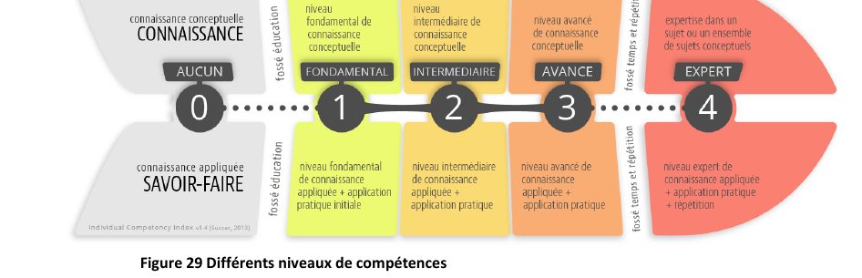
This figure from the thesis highlights the importance of the skills required for effective BIM tool utilisation. The transition from CAD to BIM is not merely a software issue; it is an evolution of working methods, project logic, and expectations of the draughtsman.
Priority Areas for Training
- The parameterisation of bar shapes and rebar families. Mastering the creation and modification of these elements is crucial for adapting to the specificities of each project. The use of parametric families in software like Revit allows for great flexibility.
- Managing views and filters to produce legible drawings. The 3D model contains a massive amount of information. The ability to extract and represent only what is relevant for a given drawing, using filters and view templates, is a key skill.
- Schedules and the coding of references. The automation of these processes is a major benefit of BIM. Understanding how to extract, organise, and link them to the model is essential to ensure their accuracy and consistency.
- Level of Detail: Not everything needs to be modelled in 3D. This is a fundamental point of caution. Unnecessarily detailed modelling (Level of Detail - LOD) can make the model cumbersome and complicate collaboration, without providing proportional added value. ISO 19650 encourages a clear definition of information requirements to avoid this overload.
Recommended Method
- Start with simple elements (beams, common walls) before complex junctions. This progressive approach allows for gaining experience and confidence before tackling more significant technical challenges, such as special foundations or non-standard structural elements.
- Create a library of standard shapes and details. Capitalising on past experiences and proven solutions accelerates production and ensures a degree of standardisation. These libraries can be shared within the design office.
- Retain a 2D detail when 3D adds no value. 3D modelling is a means, not an end in itself. If a detail is clearer and quicker to produce in 2D (for example, very dense and repetitive secondary reinforcement), this approach should be prioritised.
- Have initial drawings reviewed by an experienced CAD draughtsman. This cross-validation step is essential to ensure that representation conventions are adhered to and that legibility for the contractor is maintained.
Concrete Case in a Design Office
In a medium-sized structural engineering design office, the transition to BIM for rebar detailing often presents practical challenges. Let's imagine a residential reinforced concrete building project. The calculation department has produced the design notes, and the architect has provided the initial formwork drawings.
Traditionally, the CAD draughtsman would have drawn each bar, manually calculated the schedules, and visually coordinated the views. With BIM, the process is different.
- Structural Modelling: Engineers begin by modelling the load-bearing structure (columns, beams, slabs, walls) using parametric objects.
- Reinforcement Modelling: The BIM draughtsman then integrates the reinforcement directly into this 3D model. For a slab, instead of drawing lines, they will place welded mesh or bar mats with their properties (diameter, spacing, direction, cover). For a beam, they will place the longitudinal steel and the links/stirrups according to the calculation results.
- View Management and Layout: From the 3D model, the draughtsman automatically generates the necessary sections, elevations, and plan views. They use filters and view templates to display only the reinforcement relevant to each drawing, thus ensuring legibility.
- Schedules and Quantities: Reinforcement schedules are extracted directly from the model, automatically listing the bars, their lengths, diameters, and weights. Any change in the model will update these schedules in real-time.
- Clash Detection: Regular checks are performed to detect clashes between the reinforcement itself (excessive density), or with other elements such as openings (MEP ducts, stair voids). Tools like Navisworks can be used for this, by federating the different models (structure, MEP, architecture).
This scenario demonstrates how BIM adds value through automation, precision, and early coordination capability, thereby reducing errors and delays on site.
Best Practices / Common Errors
| Best Practices | Common Errors |
|---|---|
| Define a project template specific to rebar detailing (dimension styles, hatch patterns, rebar types). | Using the software's default template without customisation. |
| Model reinforcement in phases: main structure, then details, to manage complexity. | Attempting to model everything at once, leading to confusion. |
| Use clear and standard annotations and dimensions for site legibility. | Relying solely on 3D without producing interpretable 2D documents. |
| Regularly check consistency between the model and extracted drawings. | Neglecting manual verification, blindly trusting automation. |
| Collaborate openly with other trades via the IFC format and BCF (BIM Collaboration Format). | Working in silos, without sharing the model or communicating changes. |
| Optimise the Level of Detail (LOD) of reinforcement according to project needs. | Modelling every small tie or detail that adds no constructive value. |
| Continually train draughtsmen on BIM tools and methods specific to rebar detailing. | Believing that a basic knowledge of the software is sufficient to master BIM rebar detailing. |
Step-by-Step Method
- Template and Structural Model Preparation: Ensure you have a BIM project template adapted to your rebar detailing conventions (bar families, annotation styles, cover types). Import or link the initial architectural and structural model (in IFC or native format) to have the formwork elements available.
- Modelling Main Reinforcement: Begin with the most important and regular elements: slabs, walls, main beams, columns. Use the reinforcement placement features by mat, rebar path, or by object for longitudinal and transverse steel.
- Detailing and Adjusting Secondary/Special Reinforcement: Then integrate detailed reinforcement, links, corner reinforcements, localised bending reinforcement, and complex elements (junctions, corbels, etc.). This is where the draughtsman's expertise is paramount for optimisation and constructability.
- Generating Views, Plans, and Sections: Create 2D views (plans, sections, elevations) directly from the 3D model. Apply view templates to control visibility and graphic rendering. Don't forget detail views for complex areas.
- Annotation, Dimensioning, and Schedules: Annotate the drawings with necessary information (diameters, spacings, references). Dimension the covers and effective lengths. Automatically generate reinforcement schedules that will be updated with the model.
- Verification, Coordination, and Export: Perform consistency and clash checks (interferences) within the model and with other models (Navisworks). Use the BCF format to communicate detected issues. Export deliverables in PDF format for drawings, and potentially in IFC for the reinforcement model for overall coordination or for the contractor.
Points of Vigilance
- Software Performance: 3D reinforcement models can become very heavy, especially on large projects. Ensure you have a powerful workstation and optimise the model (deactivate visibility of unnecessary reinforcement, use low levels of detail during work).
- Quality of Incoming Data: A poor quality architectural or structural model will directly impact reinforcement modelling. Upfront collaboration is essential.
- Continuous Training: BIM software evolves rapidly. Technological watch and continuous training are indispensable for maintaining efficiency and productivity.
- Intellectual Property and Sharing: BIM models contain a lot of information. Clearly define data sharing and intellectual property protocols with other project stakeholders, referring to the principles of ISO 19650.
- Resistance to Change: The transition to BIM requires a significant adaptation effort. Support your teams in this process with training, support, and transparent communication.
Key Takeaways
- Rebar detailing expertise is retained: only the tool changes.
- Automatic consistency and schedules are the real gains.
- Model only what is useful: 2D detailing still has its place.
Article based on the professional thesis "BIM transition and optimised deployment, applied in an engineering firm".
Mickael Quinart, PALLADION
Want to go further?