
BIM · 8 min read
BIM process, coordination and standards: IFC, buildingSMART and collaboration
By Mickael Quinart · 9 October 2026
From the overall BIM process to multi-disciplinary coordination: standards, IFC, buildingSMART and a collaborative project method.
As a BIM/CAD consultant at PALLADION, I am delighted to guide you through the fundamentals of the BIM process. This article aims to be a comprehensive educational guide to understanding and implementing an effective and collaborative BIM approach.
The General BIM Process
An effective BIM process is a loop: the decision to adopt BIM, configuration (guides, procedures, charter), modelling, interference detection and resolution, model coordination, production optimisation, 'Approved for Construction' model, followed by feedback and knowledge capture.
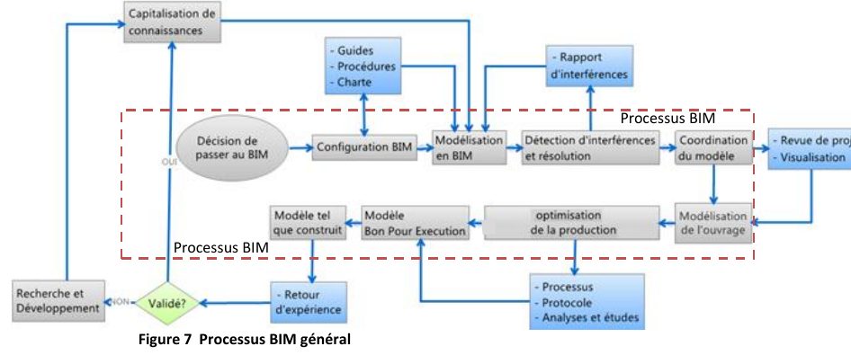
This continuous improvement loop is what distinguishes a true BIM process from simple 3D production. It highlights the importance of iteration and constant adaptation to achieve BIM maturity. Integrating this philosophy is essential for transforming traditional design and construction practices.
Standards to Speak the Same Language
BIM collaboration relies on open standards, primarily championed by buildingSMART: the IFC format for model exchange, IDM and MVD to define what information to exchange and when, the bSDD dictionary for properties, and BCF for exchanging coordination observations.

Without these standards, each stakeholder remains confined to their software; with them, the model becomes the common medium for exchanges. Adopting these standards is crucial for interoperability, allowing different software (such as Revit, ArchiCAD, Tekla Structures, Civil 3D for modelling; Navisworks, Solibri for coordination and clash detection) to communicate and exchange data fluidly and non-proprietarily. The ISO 19650 standard structures these information management processes throughout the entire asset lifecycle, leveraging these open formats.
Building a Collaborative Project
The collaborative project method in BIM is organised around three layers:
- Strategy: establishing modelling standards, resolving intellectual property issues, establishing communication protocols.
- Process: establishing project scope, identifying stakeholders, model uses, and the team's BIM capabilities, setting collaborative objectives.
- Technology: identifying software solutions, exchange capabilities, and the network environment.
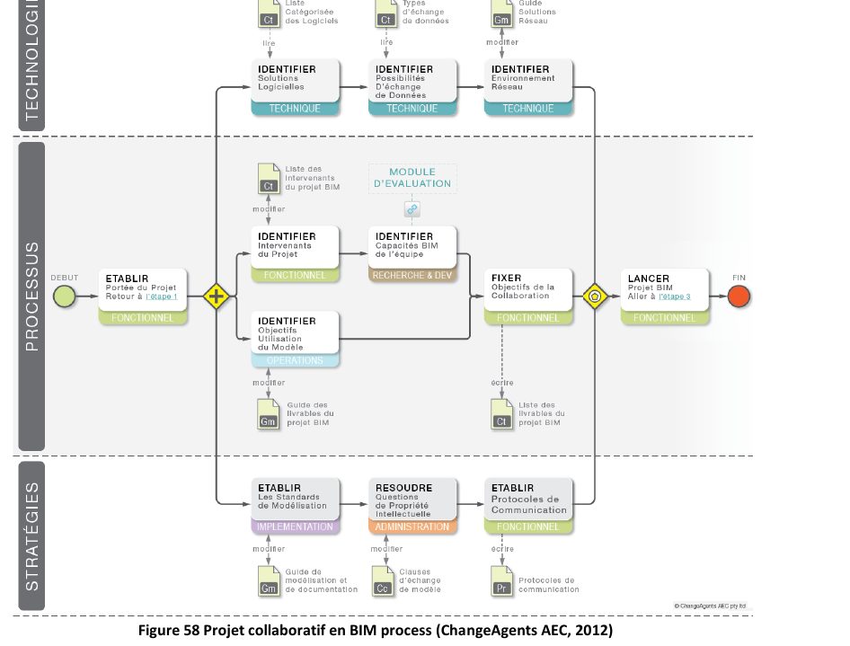
This tripartite structure is fundamental for structuring any BIM approach. It ensures that objectives (Strategy), methods (Process), and tools (Technology) are aligned for optimal collaboration and high-quality information production. The ISO 19650 standard precisely details roles and responsibilities, as well as information management at each project stage, reinforcing the importance of rigorous strategic and processual planning.
Good Coordination Practices
- Formalise a BIM Execution Plan (BEP) from the outset.
- Define a coding system and levels of development per phase.
- Organise regular model reviews.
- Track interferences and their resolution.
- Check the quality of exchanged IFCs before each distribution.
Practical Example in a Design Office
In a structural design office, BIM integration leads to a significant transformation of working methods. Rather than receiving 2D architectural drawings and then modelling the structure, the office receives an architectural model in IFC format.
- Receipt and Verification: The BIM Project Lead begins by verifying the received architectural IFC model. They ensure its compliance with the requirements defined in the BIM Execution Plan (BEP) in terms of geometry, classification (standard IFC), and the presence of necessary information (element properties, levels, etc.). Tools such as Solibri or Navisworks are used for this initial analysis.
- Structural Modelling: The structural modelling team (using Revit or Tekla Structures) uses the imported architectural model as an underlay. They model columns, beams, slabs, and foundations, respecting architectural constraints and structural calculation requirements. The goal is to create a structural model that seamlessly integrates into the overall building environment.
- Coordination and Clash Detection: Once the structural model is advanced, it is exported as IFC and federated with the architectural model (and potentially the MEP model if already available) in clash detection software (e.g., Navisworks Manage). Automated checks identify interferences between elements (e.g., a beam passing through a ventilation duct or a column appearing in a window).
- Collaborative Resolution: Detected clashes are exported in BCF (BIM Collaboration Format). These BCF reports are shared with the architect and MEP engineers. Each report contains a view of the issue, a description, and a proposed solution or request for clarification. A BIM coordination meeting, usually weekly, is organised to discuss these clashes and decide on necessary adjustments. For example, the architect might move a partition, or the structural engineer might adjust a beam soffit.
- Updates and Iteration: After the meeting, each team updates their respective model based on the decisions made. The coordination process is then repeated to ensure that corrections have not created new problems and that the entire project is consistent. This iterative loop guarantees the quality of the federated model and anticipates site problems.
- Deliverable Production: Once coordination is complete, the "Approved for Construction" structural model is used to generate 2D construction drawings (formwork, reinforcement), schedules, and quantities, ensuring greater reliability and time savings compared to traditional methods.
This case illustrates how BIM transforms the design office from a simple drawing producer into a key player in the coordination and optimisation of construction projects, relying on standardised tools and processes.
Good Practices / Common Mistakes
| Good Practices | Common Mistakes |
|---|---|
| Start with a clear BIM Execution Plan (BEP). | Absence of BEP or BEP too vague/not followed. |
| Define BIM uses from the outset. | Modelling without clear objectives, just for 3D. |
| Use open standards (IFC, BCF, etc.). | Remaining locked into a proprietary format. |
| Check the quality of incoming IFC models. | Not verifying received IFCs, leading to errors. |
| Organise regular coordination meetings. | Ad-hoc coordination, without method or follow-up. |
| Track and monitor clash resolution. | Identifying clashes but not resolving or tracking them. |
| Capitalise on lessons learned. | Repeating the same mistakes project after project. |
| Continuous team training. | Neglecting staff upskilling. |
| Ensure consistency of element properties. | Using inconsistent or missing properties. |
| Define a structured CDE (Common Data Environment). | Disorganised data management (server, email). |
Step-by-Step Method
Here is a structured 5-step method for implementing and managing a BIM process:
1. Define Needs and Objectives (Strategy):
* Clearly identify why you want to use BIM: what problems need solving? What are the expected benefits (error reduction, time savings, better communication, etc.)?
Draft the project's BIM Execution Plan (BEP)*, defining roles, responsibilities, Levels of Development (LOD/LOIN), deliverables, specific BIM objectives (uses), and exchange protocols.
* Establish an internal modelling charter to standardise practices within your team.
2. Set Up the Collaborative Environment (Technology & Process):
* Select modelling software (e.g., Revit, ArchiCAD), coordination software (e.g., Navisworks, Solibri), and data management software (e.g., Autodesk Construction Cloud, Trimble Connect, Kairnial).
Configure a Common Data Environment (CDE)* according to ISO 19650 to centralise and organise all project data and models. Define the folder structure and access rights.
* Ensure that exchange formats (IFC, BCF) are correctly configured in all software.
3. Modelling and Initial Production (Process):
* Different teams (architecture, structure, MEP, etc.) model their respective disciplines, adhering to the charter and the BEP.
* Regularly export models in IFC to make them interoperable and shareable.
* Ensure that necessary information (properties, classifications) is correctly integrated into model elements.
4. Coordination and Interference Detection (Process):
* Federate the IFC models from different disciplines in the coordination software.
* Perform automated clash detections to identify geometric interferences (e.g., a pipe passing through a beam).
* Analyse the results and create clash reports or BCF issues for each interference, describing the problem and suggesting solutions.
5. Resolution, Iteration, and Knowledge Capture (Process & Strategy):
* Organise regular BIM coordination meetings to discuss and resolve clashes with all stakeholders. Use BCF issues to track decisions and responsibilities.
* Each team updates their model based on resolutions. The detection and resolution process is repeated until major clashes are eliminated.
* Document lessons learned and identified good practices to improve processes on future projects. Update the internal BIM charter and BEP if necessary.
Key Considerations
- Resistance to Change: Adopting BIM requires deep cultural change. Support your teams through training and communication about the benefits.
- Data Quality: BIM relies on information. Incomplete, erroneous, or unstructured data (properties, classifications) can render the model unusable for its defined purposes.
- True Interoperability: Although IFC is a standard, its implementation can vary between software. Always test data exchange between your tools and those of your partners early in the project.
- Over-modelling/Under-modelling: Modelling too many unnecessary details for the defined use is a waste of time and resources. Conversely, under-modelling will prevent the achievement of objectives. The LOD (Level of Development) or LOIN (Level of Information Need) must be precisely defined and adhered to.
- Version Management: With multiple contributors and frequent updates, rigorous version management of models within the CDE is crucial to avoid confusion and errors.
- Contractual Responsibilities: Roles and responsibilities must be clearly defined in contracts and the BIM Execution Plan to avoid disputes in case of problems.
Key Takeaways
- The BIM process is a loop of continuous improvement.
- IFC, IDM/MVD, bSDD, and BCF enable interoperability. The ISO 19650 standard governs this information management.
- A collaborative project is organised into strategy, process, and technology.
- Controlling the quality of IFCs is essential: test this site's free viewer and BIM analysis.
Article based on the professional thesis "BIM transition and optimised deployment, applied in an engineering firm".
Mickael Quinart, PALLADION
Want to go further?