
BIM · 9 min read
Levels of detail ND1 to ND4: model just what is needed at each stage
By Mickael Quinart · 9 October 2026
Concepts, systems, products, as-built: levels of detail ND1 to ND4 to avoid over-modelling and control time spent.
Over-detailing, an enemy of profitability: Optimising BIM modelling with Levels of Detail
Modelling details too early that will subsequently change leads to a considerable loss of time. Conversely, a model that is too lean during the detailed design (PRO) phase does not allow for reliable quantities or effective coordination. The key to efficient and profitable BIM modelling lies in mastering levels of detail. These establish the appropriate level of geometric precision and information for each project phase, thus ensuring that the modelling effort is proportionate to actual needs.
As a BIM/CAD consultant at PALLADION, I regularly observe that one of the main pitfalls encountered by project teams is the temptation to over-detail or, conversely, to create an overly simplistic model. This is why a clear understanding and rigorous application of levels of detail are fundamental to optimising processes, controlling costs, and ensuring the quality of BIM deliverables.
The four levels
To frame this progression of detail, a standardised framework has been developed, often adapted from North American LOD (Level of Development) or the LOIN (Level of Information Need) of ISO 19650. At PALLADION, we favour a pragmatic approach, structured around four main levels, applicable to both geometry (LOG - Level of Geometry) and information (LOI - Level of Information).
| Level | Title | Typical Phase | Content |
|---|---|---|---|
| ND1 | Concepts | Sketch Design | Volumes, surfaces, site layout |
| ND2 | Systems | Pre-Design / Concept Design | Building systems, thicknesses, main networks |
| ND3 | Products | Detailed Design / Execution Design | Defined objects, precise dimensions, technical properties |
| ND4 | As-built | As-built Documentation | Installed products, manufacturer references, operational data |
These levels combine geometry (LOG) and information (LOI): an object can be geometrically simple but rich in properties, or vice versa. For example, a column in the Concept Design phase (ND2) will be a simple volume but could already contain information about its fire resistance. In the Detailed Design phase (ND3), its geometry will be more precise (e.g., IPE, HEA section) and specific material properties will be added.
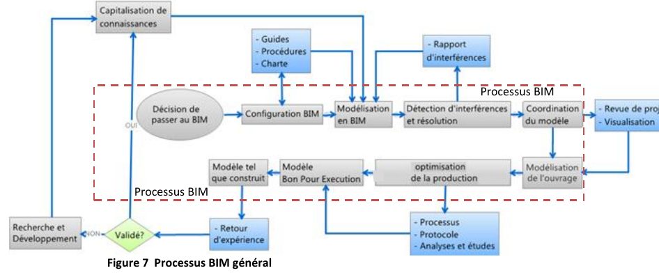
This figure clearly illustrates the progressive evolution of the model, from initial design to the operational phase, highlighting the importance of adapting the level of detail at each stage.
The golden rule: start from the use
Before modelling, the fundamental question to ask is: what will this object be used for in this phase? This is what ISO 19650 refers to as the "Level of Information Need" (LOIN). The information to be produced must be determined by the use cases defined for the model.
- For concrete quantities in the Detailed Design phase, a beam with the correct size is sufficient, without individually modelled reinforcement. Information on reinforcement (type, quantity, installation) will instead be attached to the beam as a property or via linked documents.
- For services coordination in the Concept/Detailed Design phase, nominal diameters, potential insulation, and overall dimensions are crucial. The exact brand and model of the product are not yet necessary.
- For maintenance in the As-built phase, the exact product reference (with a link to its manufacturer's data sheet), its serial number, installation date, and maintenance recommendations are much more important than its fine geometry. An equipment item can be represented by a simple volume but with all its vital information.
This use-driven approach is essential to avoid wasting resources.
Implementing the levels
The implementation of levels of detail cannot be improvised. It requires rigorous planning and standardisation.
- Define them per discipline and per phase in the BIM Execution Plan (BEP). It is crucial to adapt the requirements. For example, an architect may have different expectations for the ND3 of a façade than a structural engineering firm for the same element. The BIM Execution Plan is the reference document that harmonises these requirements.
- Create families adapted to each level. In software like Autodesk Revit, this involves developing parametric families that include visibility options to hide or display certain details depending on the view's level of detail, or creating families specific to a given level. The use of templates and pre-qualified and standardised BIM object libraries (with classifications like OmniClass or Uniformat) is highly recommended.
- Check the model against the expected level, no more, no less. Model checking tools (such as Solibri or Navisworks) can automate part of this control, by ensuring that objects contain the required properties and that their geometry complies with the requirements of each phase.
Practical example in a design office
Let's imagine a structural engineering firm working on an office building project.
In the Concept Design phase (ND2), the team models the load-bearing elements (columns, beams, slabs) as simple volumes, with their main dimensions (e.g., 30x30 cm square columns, 30x50 cm beams), and integrates information on the material type (Reinforced Concrete) and preliminary fire resistance. The objective is to verify spatial feasibility, estimate main masses for initial sizing, and coordinate general clearances with the architect and M&E services. Structural calculations are based on these global sections, without modelling the steel reinforcement.
In the Detailed Design phase (ND3), the engineer specifies the geometry of the structural elements. Columns may become specific profiles (e.g., 30x60 cm for certain load paths), and slabs may incorporate more precise penetrations. Crucially, non-geometric properties are enriched: type of steel reinforcement, mechanical properties of concrete, values of support reactions for secondary packages, information necessary for detailed concrete and steel quantities (without modelling each bar). The model is used to generate formwork execution drawings and schedules for quantities. Reinforcement is generally defined by annotations and tables extracted from the model, rather than by individual bar modelling, which would be ND4 for the structure.
In the Execution (ND3-ND4) phase, if the design office is responsible for construction supervision, the model may be enriched for reinforcement coordination, or for integrating actual execution data (for example, after a survey). For the structure, ND4 would correspond to the explicit modelling of each reinforcing bar, which is rarely done in a globalised BIM framework and is more typically handled by specific rebar detailing software.
This progressive approach avoids spending a colossal amount of time modelling reinforcement in the Concept Design phase, only to discover later that the global sections have changed, rendering that work obsolete.
Best practices / Common errors
| Best Practices | Common Errors |
|---|---|
| Define clear LOIN/NDs from the BIM Execution Plan, by use, by phase, and by discipline. | Ignoring or underestimating the definition of levels of detail, relying on everyone's "common sense". |
| Train teams on the correct application of NDs and parametric modelling tools. | Assuming everyone understands the concept without training or clear guidelines. |
| Use parametric BIM object libraries and templates adapted to NDs. | Manually modelling every detail or using generic non-parametric families. |
| Regularly check model compliance with required NDs. | Waiting until the end of a phase to discover massive over-detailing or under-detailing. |
| Adopt a collaborative approach and communicate detail expectations among stakeholders. | Working in silos, each discipline modelling according to its own internal criteria. |
| Prioritise information over geometry when relevant (e.g., for maintenance). | Seeking a perfect 3D representation for every use, even if a property is sufficient. |
Step-by-step method for managing levels of detail
For effective implementation, follow these structured steps:
- Identify project use cases and deliverables: Before modelling anything, determine what the model will be used for at each phase (estimations, energy analyses, coordination, execution drawings, as-built documentation...). This is the basis of your "Level of Information Need" (LOIN).
- Define Levels of Detail (ND/LOD) by discipline and by phase: For each identified use case, specify the required geometric level of detail (LOG) and level of information (LOI) for key elements of each discipline. Record these requirements in the project's BIM Execution Plan, ideally in a table or matrix for clarity.
- Prepare object libraries and templates: Develop or adapt BIM object families (e.g., in Revit) that can evolve in detail or are specific to an ND. Set up project templates with view filters, graphical levels of detail, and custom properties to facilitate modellers' work.
- Model according to the defined NDs: Modelling teams must scrupulously follow the ND requirements for each element. This involves using appropriate objects and not adding details or information that are not required for the current phase.
- Check and validate model compliance: At regular intervals and at each phase milestone, perform quality checks. Use model review software (such as Navisworks, Solibri) to verify compliance with NDs (presence of information, geometric conformity). Open exchange formats like IFC enable interoperability for these checks.
- Capitalise and adjust: Document lessons learned and adjust processes for future projects. Feedback is invaluable for refining ND definitions and the effectiveness of their application.
Points of vigilance
- Communication: The definition and application of NDs must be the result of collaboration and constant communication among all project stakeholders (client, architects, design offices, contractors). Tools like BCF (BIM Collaboration Format) are excellent for discussing identified shortcomings or over-detailing.
- Flexibility: Although NDs are essential for structuring, a certain degree of flexibility must be maintained. Project modifications may necessitate adapting NDs for certain elements.
- Model size: Unnecessary over-detailing can make models heavy and difficult to handle, slowing down software and exchanges. Good ND management ensures performance.
- Responsibility: The BIM Execution Plan must clearly assign responsibility for the production of each ND to the relevant discipline.
Key takeaways
- ND1 concepts, ND2 systems, ND3 products, ND4 as-built.
- Geometry and information evolve separately, but in concert, according to the uses of the model.
- We model for a specific use, not for the beauty of the model or out of habit.
- ISO 19650 and the concept of LOIN (Level of Information Need) are essential references for structuring this approach.
- The BIM Execution Plan is the key document for defining and governing levels of detail on a project.
By mastering levels of detail, you transform BIM from a mere technology into a powerful lever for optimising profitability and quality for all your projects. This is a strategic approach for any construction professional engaged in the digital era.
Article based on the professional thesis "BIM transition and optimised deployment, applied in an engineering firm".
Mickael Quinart, PALLADION
Want to go further?